Ensure the input selection switch is in the upward position (Input A/Bluetooth®).
Press and hold the encoder knob for 3 seconds to access product controls.
Once the menu is open, scroll down to Input A/BT.
Using the rotary encoder, click to open the Input A/BT settings and ensure Bluetooth® is selected.
Scroll and select Back to return to the main menu.
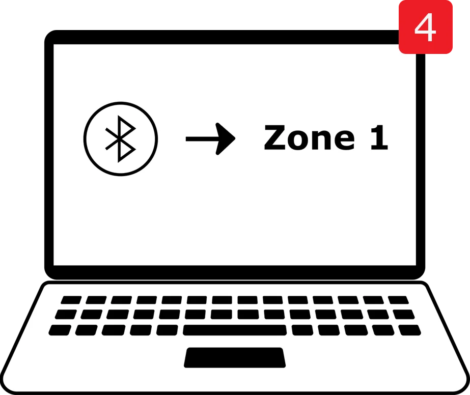
From the main menu, scroll to BTSettings and click the encoder to open the menu. Note: The default Name is Zone 1. To change this, select Name and scroll down to select your desired Zone Name.
Select Connect. The Bluetooth® indicator light will begin blinking.
Navigate to the Bluetooth® settings on your source device and connect to the Zone you chose in the previous step.
Your device is now connected to Bluetooth® wireless technology.
Settings and Controls
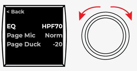
To access additional product controls, press and hold the rotary encoder for at least 3 seconds.
To select a menu option, rotate the rotary encoder until your desired option is highlighted, then press the rotary encoder to display more settings.
EQ: Use the rotary encoder to select your desired EQ preset.
Output: Select Mono for all audio signals to be summed together. Select Stereo for the audio signals to be separated.
Note: This option is available for 250BL models only.
Page Mic: Select Norm for the Page Mic to follow the output volume. Select Bypass to increase the output volume to max.
Page Duck: Select the level you prefer the audio to duck under the page signal when Page is in use.
Front Mic: Select whether the Front Mic will Duck under or Mix with the music source.
Aux Page: Select Yes for the auxiliary source to allow paging. Select No to disallow paging from the auxiliary source.
Src Sel:
When a ControlCenter CC-1 zone controller is connected, select Front to re-enable source selection through the amplifier’s front toggle switch.
When a ConrolCenter CC-2 zone controller is connected, select Remote to prioritize source slection through the remote’s controls.
When no ControlCenter zone controller is connected, the source select is controlled by the front switch regardless of which option is selected.
Dyn EQ: Turn Dynamic EQ On or Off. Dynamic EQ automatically adjusts bass levels based on the volume level.
Input A/BT: Select BT to prioritize a source connected via Bluetooth® wireless technology. Select A to override the Bluetooth® enabled source. A is the default source.
Input A Setup
Ensure the input selection switch is in the upward position (Input A/Bluetooth®).
Press and hold the encoder knob for 3 seconds to access product controls.
Using the rotary encoder, scroll down to Input A/BT and click to open more menu options.
Select A. A check mark will appear next to your selection.
Scroll and select Back to return to the main menu.
Insert RCA cables from your device into the INPUT A connectors on the rear panel.
Your device is now connected to Input A.
Input B Setup
Ensure the input selection switch is in the downward position (Input B).
Insert RCA cables from your device into the INPUT B connectors on the rear panel
Your device is now connected to Input B.
Connecting Loudspeakers
Veritas 2160BH and 1100BH
Wire the 3-pin Euroblock according to your desired operating voltage and attach it to the connector on the rear panel.
(Wire top and bottom for 70V and center and bottom for 100 V)
70V
100V
Veritas 2160BL and 250BL
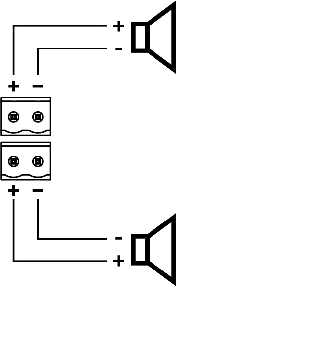
Wire the 2-pin Euroblock
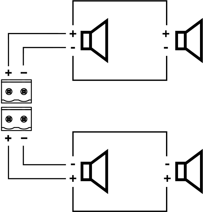
Make a single loudspeaker connection as seen in Diagram 1 or connect two loudspeakers in parallel as seen in Diagram 2.
When connecting the loudspeakers in parallel:
Connect the wires from the amplifier to the matching positive (+) and negative (–) terminals on the first loudspeaker.
Connect the positive (+) and negative (–) terminals of the first loudspeaker to the positive (+) and negative (–) terminals of the second loudspeaker.
Single 4Ω - 8Ω loudspeaker:
Two 8Ω loudspeakers in parallel
CAUTION: Do not connect more than two loudspeakers together in this manner. Doing so could damage the amplifier
More Information
Please refer to the installation guide and owner’s guide for information on other topics, including: