A Guided Walkthrough from Design to Configuration
Congratulations on the purchase of your new Bose Professional MSA12X Powered Beam-Steering Array loudspeaker.
This page is meant to serve you as a getting-started point. Simply progress through each section to deploy your MSA12X system.
We start with a review of the MSA Design Tool and how it can be used to provide optimal coverage to your audience areas. That’s followed by an unboxing of the MSA12X and a review of what is included. Next, essential pre-installation steps are provided to reduce time spent on-site. When you’re ready to assemble and mount your arrays, we’ve got you covered with best practices for mounting and installation, and we end with how ControlSpace Designer can be utilized to dial in your configuration.
Thank you for choosing the MSA12X.
design
MSA Design Tool
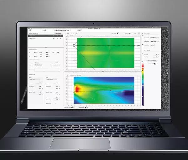
Create custom-fit designs in less time. MSA Design Tool software helps AV system designers produce precise MSA12X sound system designs quickly. The Array Tool features an intuitive interface and familiar workflow, so it requires minimal training. Using the direct-field calculation engine, you can quickly trial different MSA12X configurations, placements, and coverage formations to best match the needs of the venue.
Design Guide
If you require an offline resource to aid you in the design and deployment of your MSA12X system, please download this helpful guide, otherwise, you can continue down this page to get you up and running.
Provided below is an example of how the MSA Design Tool can be used to model a venue and optimize the coverage of MSA12X arrays. In this example, a pair (L/R) of 2-module arrays are configured to provide coverage to the main floor and balcony of an auditorium for speech applications.
Venue Modeling
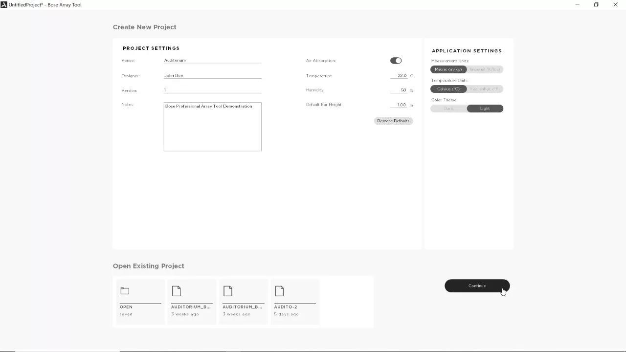
Step 1: Launch the MSA Design Tool and define your project settings. Click Continue when you are ready to proceed.
Note: The Default Ear Height is set to 1 m (3.28 ft) which is suitable for a seated audience. This value can be later modified in your venue model
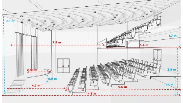
Auditorium: elevation view
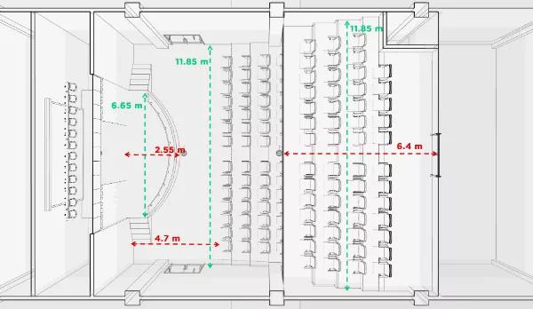
Auditorium: plan view
Next, create a 2D model of the acoustic space where your MSA12X modules will be installed. This is accomplished either by using measurements gathered from site plans such as plan and elevation views or by taking measurements at the site itself. In this example, three surfaces will be modeled: the stage, main floor, and balcony.
Step 2: By default, you begin with 1 surface. You may either enter values into the properties panel or use your mouse to adjust the points in Plan and Side Views.
Note: The Ear Height can be adjusted in the Properties Panel and is represented by a dashed line in the Side View. In this example, the stage is using an ear height of 1.75 m (5.74 ft).
Step 3: Double-click on the surface and give it an appropriate name. Press Enter after renaming the surface.
Step 4: Click the Add a New Surface button and repeat Steps 2 and 3. Repeat these steps until each area of the venue has been modeled.
Step 5: At this point, it’s a good idea to save your work. Ctrl-S will bring up your Save Project window.
Loudspeaker Positiong and Optimizing Coverage
Step 1: Click on the Speaker/Analysis tab, and click on the Add a New Loudspeaker button. Double-click the array to rename it. Press Enter after renaming the array.
Note: This system example will consist of a left and right array. After configuring the first array, Focus on optimizing the coverage for one array and then use standard keyboard shortcuts to copy and paste another array.
Step 2: Adjust the Array Position. You may either enter values into the Array Properties panel under the Array Position section or use your mouse to adjust the array in the Plan and Side Views.
Note: Z consists of a Top, Center, and Bottom coordinate. Top represents the Z coordinate at the top plate of the array in the venue, Center the array midpoint, and Bottom the Z coordinate of the bottom plate of the array. You only need to specify one of these values.
The pitch can be modeled for mounting the MSA12X on angled surfaces only. Its included mounting hardware does not support vertical angles, but an optional yaw bracket will allow you to securely position the array at ±6 degree increments between 12 and 90 degrees. If you intend to use the included yaw brackets, you may also specify the yaw angle here.
Step 3: Under the Array Configuration section, specify how many modules will be used in an array and select between Single or Dual beams. Dual beams are used in this example to provide coverage to both the main floor and balcony.
Note: Delay is available for time-aligning arrays relative to the position of other loudspeakers in the venue.
Step 4: Select the desired beam shape for both the Main and 2nd beams. If you are working with a single beam, you will only have one selection to make.
Note: In this example, a Steer/Spread or Raked Floor could be used for both the Main Floor and Balcony. Experiment to find what ultimately sounds the best for your venue.
Tip: Use your mouse wheel to zoom in or out in the Plan and Side Views. Hold Ctrl and left-click the mouse to pan.
A review of the beam shapes and their definitions are provided below:
Step 5: Adjust the Beam Shape properties. Values may be entered into the Beam Shape Array Properties or you can use your mouse in the Side View to adjust the top and bottom throw lines using the handles as illustrated. Aim the beam at the dashed line (listener ear height) for each surface. In this example, the Main beam is first aimed at the main floor and then the 2nd beam is aimed at the balcony.
Note: Depending on your venue, you may choose to use one of the other beam shape algorithms to begin.
By default, array gain is initially set at 0 dB, which is equivalent to 1 watt. Before moving on to view the SPL map, it is recommended to invoke the Set Max Gain function.
Step 6: With the array selected, press the Set Max Gain button. Notice how the Gain parameter under the Array Configuration changes.
The Sound Pressure Level (SPL) Map option visualizes direct field coverage in a venue for various array placement and beam shape configurations. Direct field coverage describes the direct path between the loudspeaker and the listener and does not include the effects of reflections or reverberation. SPL values in dB are mapped to a color scale on the right edge of the graphical views.
Step 7: Under the SPL Mode, change the resolution to High and disable Auto-adjust.
High setting provides the finest resolution and smoothest color transitions for data in the SPL map.
When Auto-adjust is set to On, the range of SPL values in graphical views, the range on the color scale and the lower and upper SPL values are automatically and continuously adjusted in response to any change in the range present in the data. Leaving this On can result in having to repeatedly change the Upper and Lower SPL values as you make adjustments to the array.
By default, the Upper and Lower SPL values are 112 dB and 80 dB respectively, and due to such a wide range, it can be difficult to interpret the SPL map. Better results are seen when the delta between the Upper and Lower limits is between 10 – 20 dB.
Step 8: You may adjust the color scale sliders by moving the handles or you can type in values into the Upper and Lower SPL fields.
In some cases like this one, having overlapping areas can make it difficult to see what is happening on lower levels when looking at the Plan view.
Step 9: Click on the Venue tab, disable the Balcony view, and go back to the Speakers/Analysis tab. Make adjustments to the SPL properties panel as necessary. You can click in between the upper and lower sliders to adjust the overall range while maintaining the same delta.
In the plan view, the coverage for the entire venue is shown regardless of which array is selected. In the side view, only the coverage for the selected array is shown. If an array is not selected, side view coverage defaults to the center axis of the venue.
Step 10: Deselect the array to view coverage results at the center axis of the venue.
Step 11: When you are satisfied with the coverage of your first array, Ctrl-C/Ctrl-V to create and paste a copy. Rename the array and move it to its intended location.
Step 12: Click on the Recalculate button to view updated results. Make adjustments to the color scale as necessary. In this example, we can view the median value between the upper and lower range from the loudspeaker as 88 dB.
UNBOX
Discover what is included with your purchase of the MSA12X.
Package Contents
pre-install
Discover what is included with your purchase of the MSA12X.
Recommended Software and Hardware
Initial Network Setup
Updating Dante Firmware on the MSA12X
Updating ControlSpace Firmware
Connect, Initial Configuration, and Label
Cable & Mount
test
The MSA12X can be installed by one or multiple installers. The multiple installer method requires building arrays on the ground and attaching the entire assembly to the mounted wall bracket.
Best results are observed when using multiple (2-3) installers, so that is what this section will focus on. For instructions on the single installer method, please refer to the MSA12X installation guide.
CAUTION
- Each MSA12X module weighs 14.5 kg (32 lbs). Use caution when lifting to avoid injury and/or damage to the loudspeaker.
- DO NOT place the MSA12X resting on its grille.
- When installing the MSA12X in an alcove, leave a minimum of of 0.3m (1 ft) clearance on the top and bottom of the array.
Install Loudspeaker
Configure
Associate DSP and MSA12X
Adjust Input Settings
Send Beam Settings
Adjust Beam Gain and Beam EQ
Beam Preset
Power On State
Assign Beam Preset to Parameter Set
Final Steps